4.1 Relationship between switch and fuse
| Conventional heating current of switch (A) |
Matched fuse | Rated voltage (V) | Fuse current value (A) |
| 160 | NT00 | 380 | 4、6、10、16、20、25、32、35、40、50、63、80、100、125、160 |
| 660 | 4、6、10、16、20、25、32、35、40、50、63、80、100 | ||
| 250 | NT1 | 380 | 80、100、125、160、200、224、250 |
| 660 | 80、100、125、160、200 | ||
| 400 | NT2 | 380 | 125、160、200、224、250、300、315、355、400 |
| 660 | 125、160、200、224、250、300、315 | ||
| 630 | NT3 | 380 | 315、355、400、425、500、630 |
| 660 | 315、355、400、425 |
4.2 Main technical parameters of the switch
| Model | HR6-160 | HR6-250 | HR6-400 | HR6-630 | ||
| Rated insulation voltage (V) | 660 | 660 | 660 | 660 | ||
| Conventional thermal current (A) | 100 | 250 | 400 | 630 | ||
| Rated operating current (A) | 380V | 160 | 250 | 400 | 630 | |
| 660V | 100 | 200 | 315 | 425 | ||
| Rated making and breaking capacity (A) (at 1.05Ue) |
380V,COSΦ=0.35 AC-23B |
Connect | 1280 | 2000 | 3200 | 5040 |
| Disconnect | 960 | 1500 | 2400 | 3780 | ||
| 660V,COSΦ=0.65 AC-22B |
Connect | 480 | 750 | 1200 | 1890 | |
| Disconnect | 480 | 750 | 1200 | 1890 | ||
| Rated short-circuit current (kA) | 50 | 50 | 50 | 50 | ||
| Maximum expected peak current (kA) | 100 | 100 | 100 | 100 | ||
| Pollution level | 3 | 3 | 3 | 3 | ||
| Installation category | Ⅲ | Ⅲ | Ⅲ | Ⅲ | ||
4.3 The rated voltage of the auxiliary switch is AC 380V, the agreed thermal current is 6A, the use category is AC-15, and the rated control capacity is 300VA.
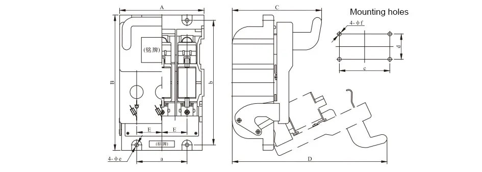
| Model | Dimensions (mm) | Installation dimensions (mm) | |||||||||
| A | B | C | D | E | a | b | c | d | Φe | Φf | |
| HR6-160/30 | 134 | 215 | 142 | 245 | 40 | 80 | 198 | 80 | 40 | Φ6.5 | Φ6.5 |
| HR6-250/30 | 184 | 280 | 162 | 320 | 60 | 120 | 260 | 120 | 60 | Φ8.5 | Φ8.5 |
| HR6-400/30 | 244 | 300 | 194 | 360 | 80 | 160 | 280 | 160 | 60 | Φ8.5 | Φ8.5 |
| HR6-630/30 | 244 | 300 | 194 | 360 | 80 | 160 | 280 | 160 | 60 | Φ8.5 | Φ8.5 |


GET A QUOTE